Mechanical Advantage of Levers Explained
Unlock the power of levers. This guide explains the mechanical advantage of levers with clear formulas, classes, and real-world examples.

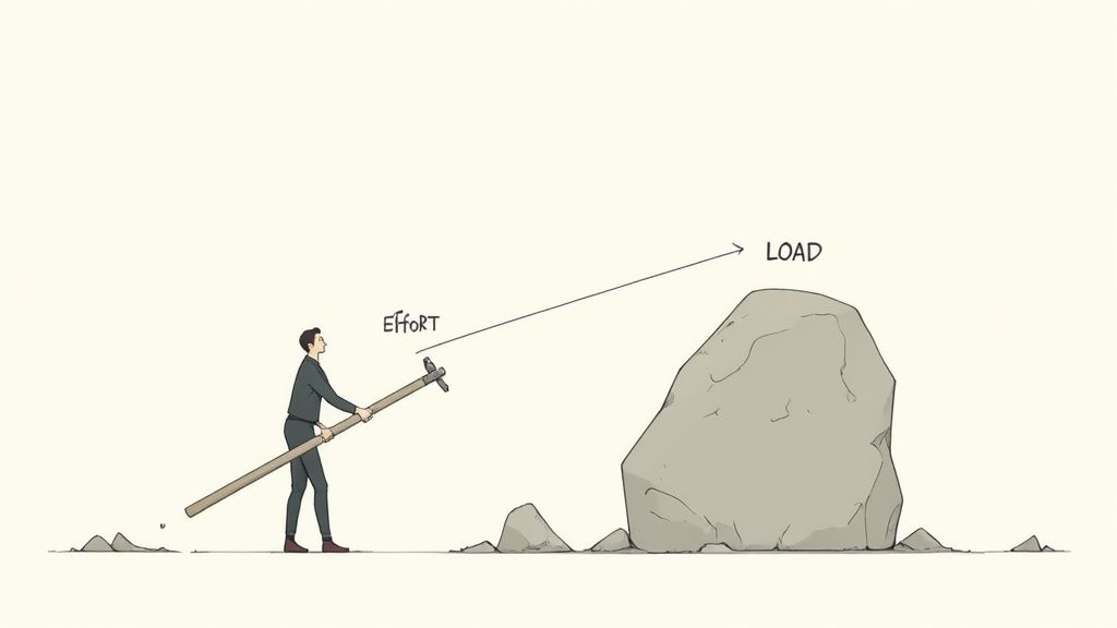
Ever used a crowbar to move a heavy rock and felt like you had superhuman strength? That's the magic of a lever at work. You've just experienced mechanical advantage—the measure of how much a simple tool can amplify your input force, turning a small push into a powerful lift.
How Levers Multiply Your Strength
It seems almost impossible, doesn't it? A small push on one end of a bar moves something incredibly heavy on the other. This isn't a new trick; it’s a fundamental principle of physics called leverage that humans have been using for thousands of years.
The lever is one of six classic simple machines, with early versions popping up around 5000 BCE as simple balance scales. By 3000 BCE, civilizations in Mesopotamia were using the shaduf—a crane-like tool—to lift water for irrigation. This ancient wisdom was perfectly captured by the Greek mathematician Archimedes, who famously said, "Give me a place to stand and with a lever I will move the whole world." You can dig deeper into the history of this powerful tool and its impact on technology.
This guide will break down exactly how these simple tools achieve such impressive results.
The Core Idea: A Force Multiplier
At its heart, mechanical advantage is all about getting more out than you put in. It's a simple ratio that tells you precisely how many times your effort is magnified. A mechanical advantage of 5, for example, means the lever is making your effort five times more powerful.
Think of it this way: a lever trades distance for force. You might have to push the handle of a car jack a long way down, but in return, the jack lifts the car a tiny bit with tremendous force.
Grasping this trade-off is the key to understanding the physics behind countless tools we use every day, from the simple to the complex. You can see this principle in action all around you:
- Bottle openers use a small lift on the handle to generate enough force to pop off a tight cap.
- Crowbars allow a single person to pry up objects weighing hundreds of pounds.
- Construction cranes and excavators apply these exact same principles on a massive scale.
This introduction sets the stage for a practical journey into the world of levers. By the time we’re done, you won't just understand the theory—you’ll be able to calculate and apply these powerful principles yourself.
The Core Principles of Mechanical Advantage
To really get a handle on the mechanical advantage of levers, we need to introduce the three key players in every lever system. The easiest way to picture this is with a classic playground seesaw—it’s the perfect, simple lever in action. Each part has a specific role, and how they’re arranged is the secret to making you stronger.
So, let's break down these three components: the fulcrum, the effort, and the load.
Meet the Key Players
First up is the Fulcrum. This is just the pivot point the lever turns around. On our seesaw, it's that central stand the plank rests on. The fulcrum is the anchor for the whole operation; without it, all you have is a board lying on the grass.
Next, we have the Effort. This is the force you put into the system. When you push down on your end of the seesaw, that push is the effort. It's the work you're doing.
Finally, there's the Load. This is the output force, or whatever object you’re trying to move. On the seesaw, the person on the other end is the load. Your whole goal is to apply just enough effort to lift that load right off the ground.
These three elements—Fulcrum, Effort, and Load—are the fundamental building blocks of every single lever, from a simple bottle opener to a giant construction crane. The relationship between them determines just how much your force gets amplified.
Before we dive into the formulas, it helps to have the terminology straight.
Key Terminology for Understanding Levers
This table sums up the essential components and forces that make any lever system work.
| Term | Definition | Example |
|---|---|---|
| Fulcrum | The fixed point around which the lever pivots or rotates. | The pin in a pair of scissors; the center of a seesaw. |
| Effort | The input force applied to the lever to move the load. | The force your hand applies to a crowbar's handle. |
| Load | The output force or resistance that the lever works against. | The heavy rock being lifted by the crowbar. |
| Effort Arm | The distance from the fulcrum to the point where the effort is applied. | The length of a wrench handle from the bolt to your hand. |
| Load Arm | The distance from the fulcrum to the center of the load. | The distance from the wheel axle to the center of a wheelbarrow's bucket. |
Having these terms down makes the physics behind the magic much clearer.
The Two Formulas That Define Mechanical Advantage
Now that we know the players, how do we actually measure this force multiplication? The mechanical advantage of levers is simply a number that tells you how many times your effort is multiplied. If you get a mechanical advantage of 10, it means your input force comes out ten times stronger.
There are two main ways to figure this out. The first one looks directly at the forces involved:
Ideal Mechanical Advantage (IMA) = Load Force / Effort Force
This formula is a straight-up comparison of the output force (the load) to the input force (the effort). If you only need to push with 10 pounds of effort to lift a 100-pound load, your mechanical advantage is 100 / 10 = 10. Pretty simple, right? This is the ideal number, assuming we're in a perfect, friction-free world.
The second formula is often more practical because it's based on distances, which are much easier to measure:
Ideal Mechanical Advantage (IMA) = Length of Effort Arm / Length of Load Arm
The Effort Arm is the distance from the fulcrum to where you apply your force. The Load Arm is the distance from the fulcrum to the load. This version reveals the fundamental trade-off of any lever: to multiply your force, you have to apply that force over a greater distance.
This principle is a cornerstone of physics and engineering. For instance, if your effort arm on a crowbar is 1 meter long and the load arm is only 0.2 meters, the IMA is 1 / 0.2 = 5. That means your output force is five times stronger than what you put in—a concept that's absolutely vital for designing everything from wheelbarrows to wrenches.
If you ever get stuck on calculations like these, an AI physics solver can be a great help by providing step-by-step explanations to walk you through the logic.
Ideal vs. Actual Mechanical Advantage
In a perfect world, both formulas would give you the exact same result. But our world has a major catch: friction. There's always a little bit of friction at the fulcrum, not to mention air resistance, and it always works against your effort, stealing a bit of its power.
This leads to a really important distinction:
- Ideal Mechanical Advantage (IMA): This is the theoretical maximum advantage, calculated using distances (Effort Arm / Load Arm). It's the best-case scenario in a frictionless system.
- Actual Mechanical Advantage (AMA): This is what you actually get in the real world, calculated using forces (Load / Effort). It automatically accounts for the energy lost to friction.
Because of friction, the AMA will always be slightly less than the IMA. The gap between them is a measure of the lever's efficiency. While IMA gives you a target to aim for, AMA tells you what the machine can truly deliver. Understanding this difference is what separates good engineering from great engineering.
Exploring the Three Classes of Levers
The real "personality" of a lever comes from how you arrange its three key parts: the fulcrum, the effort, and the load. While they all work on the same basic principle of torque, this specific layout determines whether a lever multiplies your force, gives you more speed, or just changes the direction of your push or pull. To keep them straight, we group levers into three distinct classes.
A great way to remember the setup is the mnemonic FLE—for Fulcrum, Load, and Effort. Whichever letter is in the middle tells you what component is sandwiched between the other two. For a Class 1 lever, the Fulcrum is in the middle. For Class 2, it's the Load. And for Class 3, the Effort is in the middle.
This diagram shows how these three components work together in any lever system.
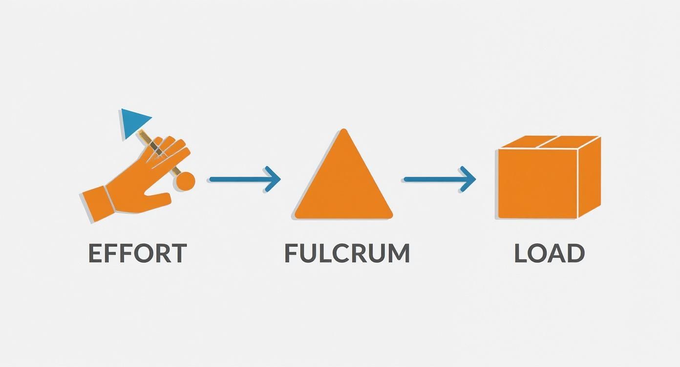
How these three parts relate to one another is what dictates the lever's function and its ultimate mechanical advantage. Let's dig into each class to see how this plays out with real-world tools.
Class 1 Levers: The Balancers
In a Class 1 lever, the fulcrum sits right between the effort and the load. This is the classic, most intuitive setup. Just picture a seesaw on a playground, a pair of scissors cutting paper, or a crowbar prying up a stubborn nail. In every case, the pivot point is in the middle, with forces acting on either side.
What makes Class 1 levers so versatile is that their mechanical advantage isn't fixed—it can be greater than, less than, or even equal to 1. It all comes down to where you place the fulcrum.
- MA > 1 (Force Multiplier): When you slide the fulcrum closer to the load, your effort arm gets longer. This setup amplifies your force, which is perfect for tasks like using the claw of a hammer to pull out a nail.
- MA < 1 (Speed/Distance Multiplier): Move the fulcrum closer to your effort, and the load arm becomes the longer one. You’ll have to push harder, but the load will move a much greater distance and with more speed. Think about how the tips of scissors travel much further than your fingers do.
- MA = 1 (Direction Changer): If you place the fulcrum exactly in the center, the lever doesn't multiply force at all. It simply changes its direction, just like a perfectly balanced scale.
This incredible flexibility is why Class 1 levers show up everywhere in tools that need a balance of power, precision, and control.
Class 2 Levers: The Force Multipliers
With a Class 2 lever, the load is always positioned between the fulcrum and the effort. This arrangement is a pure force multiplier, meaning its mechanical advantage is always greater than 1. It’s designed this way—the effort is always applied further from the fulcrum than the load is, guaranteeing a longer effort arm.
The wheelbarrow is the quintessential example. The wheel’s axle acts as the fulcrum, the heavy contents are the load, and you provide the effort by lifting the handles. You can see the same principle at work in a bottle opener, a nutcracker, or even a simple door.
In a Class 2 lever, you trade a longer distance of movement for a huge boost in force. You might lift the wheelbarrow handles a foot to raise the load by only a few inches, but that heavy load feels dramatically lighter.
Because your effort arm is always longer than the load arm, you’re guaranteed to get more force out than you put in. This design is the go-to for any job that requires moving heavy resistance with minimal strain.
Class 3 Levers: The Speed Multipliers
Finally, we have the Class 3 lever, where the effort is applied between the fulcrum and the load. At first glance, this might seem inefficient. It always has a mechanical advantage of less than 1, which means you have to apply more force than the load itself.
So, why bother? The payoff is speed and an extended range of motion.
In a Class 3 lever, the load arm is always the longest. This means a tiny, quick movement at the effort point creates a much larger, faster movement at the load end. You can find these levers all around you:
- Fishing Rods: A small flick of your wrist (the effort) sends the tip of the rod (the load) whipping through a wide arc to cast the line.
- Tweezers: Your fingers apply effort in the middle to give you fine, precise control over the tips.
- Your Forearm: The bicep muscle (effort) pulls on your forearm just below the elbow (fulcrum) to lift an object in your hand (load).
These levers sacrifice brute force for speed and dexterity, making them perfect for tasks where a wide or quick motion is far more valuable than raw power.
Comparison of Lever Classes
To pull it all together, this table gives you a side-by-side look at the three lever classes, highlighting their component arrangement, mechanical advantage, and a few common examples you’ll recognize.
| Feature | Class 1 Lever | Class 2 Lever | Class 3 Lever |
|---|---|---|---|
| Arrangement | Fulcrum is between the Effort and the Load (E-F-L or L-F-E). | Load is between the Fulcrum and the Effort (F-L-E). | Effort is between the Fulcrum and the Load (F-E-L). |
| Mechanical Advantage | Can be > 1, < 1, or = 1. | Always > 1. | Always < 1. |
| Primary Function | Versatile; can multiply force or speed, or change direction. | Multiplies force. | Multiplies speed and range of motion. |
| Common Examples | Seesaw, scissors, crowbar, pliers. | Wheelbarrow, bottle opener, nutcracker. | Fishing rod, tweezers, human forearm, broom. |
Getting a feel for these classifications is the key to understanding how tools are engineered for specific jobs. For instance, in demanding fields like construction, a Class 2 lever is a game-changer. A wheelbarrow can amplify an operator's force so well that a 50 kg load might feel like you're only lifting 10 kg, a mechanical advantage of 5. You can learn more about how these concepts fit into the broader world of simple machines.
How to Calculate Mechanical Advantage
Knowing the theory behind levers is great, but the real magic happens when you start plugging in numbers. This is where we go from abstract concepts to a concrete understanding of how much force you can actually generate.
Walking through a few calculations will show you just how potent these simple machines are. Let's get our hands dirty with the two key formulas for Ideal Mechanical Advantage (IMA). Remember, IMA is our "perfect world" calculation—it assumes no energy is lost to friction and gives us the maximum theoretical performance of a lever.
The Two Essential Formulas
The first, and most common, way to find a lever's theoretical power is by measuring the distances from the fulcrum. This is usually the easiest data to get in a real-world scenario.
IMA = Length of Effort Arm / Length of Load Arm
The second formula looks at the forces involved: the effort you put in versus the load you're trying to move. This one defines the actual force multiplication you're getting.
IMA = Load Force / Effort Force
With these two equations, we can solve for any missing piece of the puzzle, whether it's how much you need to push or the advantage a specific tool gives you. It's always a good idea to have these handy, and you can find them on any good physics formulas cheat sheet.
Let's put them to the test.
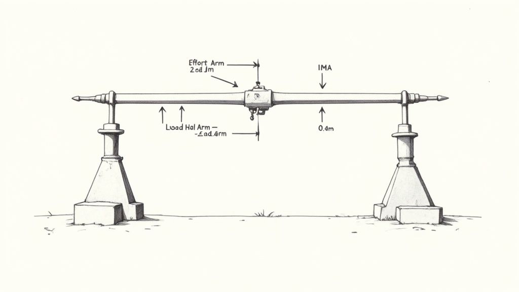
Example 1: Lifting a Boulder with a Crowbar (Class 1 Lever)
Let's say you're trying to shift a heavy boulder. You've got a sturdy crowbar that's 2 meters long and a small rock to act as your fulcrum. You wedge the crowbar under the boulder and place the fulcrum 0.4 meters from that end.
- Goal: Calculate the Ideal Mechanical Advantage (IMA).
- Knowns: Total lever length = 2 m. Load arm = 0.4 m.
First, we need to figure out the length of the effort arm. That's simply the rest of the crowbar's length.
- Effort Arm = 2.0 m – 0.4 m = 1.6 m
Now, we can pop these numbers into our distance formula.
- Formula: IMA = Effort Arm / Load Arm
- Calculation: IMA = 1.6 m / 0.4 m
- Result: IMA = 4
What does that mean? It means this setup multiplies your effort by four times! For every bit of force you put on the handle, the crowbar delivers four times that force onto the boulder.
Example 2: Using a Wheelbarrow (Class 2 Lever)
Picture this: you're hauling a load of bricks in a wheelbarrow. The weight of the bricks is centered about 0.5 meters from the wheel axle (our fulcrum). You're lifting the handles 1.5 meters away from that same axle. The bricks weigh a total of 300 Newtons.
- Goal: Find the IMA and the effort needed to lift the bricks.
- Knowns: Load Arm = 0.5 m, Effort Arm = 1.5 m, Load Force = 300 N.
Let's start by calculating the mechanical advantage from the distances.
- Formula: IMA = Effort Arm / Load Arm
- Calculation: IMA = 1.5 m / 0.5 m
- Result: IMA = 3
So, the wheelbarrow gives you a mechanical advantage of 3. Now we can use our second formula to find out how much force you actually need to apply to lift that 300 N load.
- Formula: IMA = Load Force / Effort Force
- Calculation: 3 = 300 N / Effort Force
- Rearrange: Effort Force = 300 N / 3
- Result: Effort Force = 100 N
That's the power of a Class 2 lever. You only need to apply 100 Newtons of force to lift a 300-Newton load. The wheelbarrow is doing the rest of the work for you.
Example 3: Casting a Fishing Rod (Class 3 Lever)
A fishing rod is a perfect example of a Class 3 lever. The butt of the rod pressed against you is the fulcrum. Your wrist applies the effort about 0.5 meters from the fulcrum, while the fish tugging on the line (the load) is 3 meters away.
- Goal: Find the IMA of the fishing rod.
- Knowns: Effort Arm = 0.5 m, Load Arm = 3 m.
A quick calculation with the distance formula reveals something interesting.
- Formula: IMA = Effort Arm / Load Arm
- Calculation: IMA = 0.5 m / 3 m
- Result: IMA ≈ 0.17
The mechanical advantage is far less than 1. This confirms that a Class 3 lever isn't built to make things easier by multiplying force. Instead, it's a speed and distance multiplier. A tiny flick of your wrist generates a long, fast arc at the tip of the rod—exactly what you need to send a lure flying across the water.
Advanced Concepts in Leverage and Efficiency
So far, we've been working in a perfect world—one without friction, where levers are weightless and perfectly rigid. But when we bring these concepts into reality, we bump into forces that work against us. Friction at the fulcrum, air resistance, and even the weight of the lever itself can chip away at a lever's performance.
This means the force multiplication we get in the real world is always a little less than what our neat and tidy formulas predict. Understanding this gap is what separates classroom theory from practical, real-world engineering.
Ideal Versus Actual Mechanical Advantage
All our calculations up to this point have been for the Ideal Mechanical Advantage (IMA). We find it by simply dividing the effort arm by the load arm. The IMA is the absolute best-case scenario, the theoretical maximum boost a lever can provide in a flawless system. It's the goal we aim for.
But in practice, what we actually measure is the Actual Mechanical Advantage (AMA). This is the real-world result, calculated by dividing the actual load force by the actual effort force you apply. Because things like friction are always present and steal a bit of your energy, the AMA will always be lower than the IMA.
The gap between IMA and AMA isn't a failure; it's a measure of efficiency. It tells us how much of our work is being lost to real-world imperfections.
A well-oiled, precision-built machine will have an AMA that gets incredibly close to its IMA. On the other hand, a rusty, poorly constructed lever will have a much lower AMA, meaning a lot of your effort is just being wasted overcoming friction.
Calculating Lever Efficiency
So, how do we put a number on how well a lever is doing its job? We calculate its efficiency. Efficiency is just a percentage that tells us how much of the work we put in gets converted into useful work moving the load.
The formula is refreshingly simple:
Efficiency (%) = (AMA / IMA) x 100
Let's walk through an example. Say you've designed a lever system with an IMA of 5. You set it up and measure the forces, finding that it takes 30 Newtons of effort to lift a 120 Newton load.
First, let's find the AMA from our real-world measurements:
- AMA = Load / Effort = 120 N / 30 N = 4
Now, we can plug our numbers into the efficiency formula:
- Efficiency = (4 / 5) x 100 = 80%
This result tells us that 80% of the effort you applied was successfully used to lift the load. The other 20% was lost, most likely to friction. For tricky problems like this, checking your work with an AI math solver can be a great way to build confidence.
The Power of Compound Levers
Sometimes, a single lever just won't cut it. When you need a massive amount of force multiplication, you can chain levers together to create a compound lever. In this kind of system, the output force of one lever becomes the input effort for the next.
Bolt cutters are a classic example of this principle in action.
- The Handles: When you squeeze the long handles, you're using a Class 1 lever. Your hands provide the effort, and the force is amplified at the short pivot point connecting to the jaws.
- The Jaws: This powerful output force from the handles becomes the input effort for a second, much shorter lever system right at the cutting jaws, multiplying the force yet again.
To find the total mechanical advantage of a compound lever, you just multiply the individual mechanical advantages of each lever in the chain.
Imagine the handles of the bolt cutters give you an IMA of 8, and the jaw mechanism gives you an IMA of 10. The total IMA would be:
- Total IMA = IMA₁ x IMA₂ = 8 x 10 = 80
This staggering force multiplication is what lets you slice through a hardened steel bolt using only your arm strength. You'll find the same principle at work in things like a piano's key mechanism or a heavy-duty bench vise. It’s a brilliant demonstration of how simple machines, when combined, can achieve extraordinary things.
Answering Common Questions About Levers
As you get comfortable with the physics of levers, a few key questions almost always pop up. They usually dig into the practical side of things—the "why" behind the design and the trade-offs you make when using one. Let's clear up some of the most common points to really nail down your understanding of mechanical advantage.
Getting these concepts straight is what bridges the gap between the formulas on a page and how you’d actually pick and use a lever for a specific job.
Why Would Anyone Use a Lever with a Low Mechanical Advantage?
It sounds a little backward, right? Why use a tool that forces you to apply more force than the load itself? When would a mechanical advantage of less than 1 ever be useful? The answer is all about trading force for speed.
A lever with a mechanical advantage below 1, like those in Class 3, is a speed and distance multiplier. Imagine casting a fishing rod. You make a small, quick movement with your wrist (the effort), but the tip of the rod swings through a huge arc, launching the lure much farther and faster than you could ever throw it by hand.
In these cases, you’re sacrificing brute force to gain a massive boost in range of motion and velocity. This trade-off is perfect for tasks where speed, dexterity, or reach is the real goal, not just lifting power.
A few other examples make this crystal clear:
- Tweezers: Your fingers apply more force than what's needed to pinch a tiny object, but in return, you get incredibly fine control and precision at the tips.
- A hockey stick: A short, powerful movement of the hands translates into a lightning-fast sweep of the blade, sending the puck flying.
How Does Friction Mess with a Lever?
In a perfect, physics-problem world, the Ideal Mechanical Advantage (IMA) is exactly what you’d get. But here in the real world, we have friction. For levers, this friction is most noticeable at the fulcrum—the pivot point itself. Friction is a sneaky force that always works against you.
What this means is that some of the effort you put in gets "eaten up" just by overcoming that friction, leaving less of your force to actually do the work of moving the load. Because of this, the Actual Mechanical Advantage (AMA)—what you really get—is always a bit lower than the IMA. The wider that gap between IMA and AMA, the less efficient your lever is.
What's the Real Difference Between a Force and a Speed Advantage?
Getting this distinction right is the key to truly understanding the mechanical advantage of levers. It all boils down to what you're trying to accomplish, which is usually determined by the lever's class.
Force Advantage (MA > 1): This is the classic "super strength" scenario. The lever multiplies your effort, so you can move a heavy object with less force. Think of it as a force multiplier. Class 1 levers (with a long effort arm) and all Class 2 levers are designed for this. A wheelbarrow is the perfect example—it makes a back-breaking load feel manageable.
Speed Advantage (MA < 1): Here, the goal isn't to make something feel lighter, but to make it move faster or farther. You actually put in more force than the load, but in exchange, the load end of the lever travels a greater distance and at a higher speed. All Class 3 levers, like a broom or even your own forearm, are built for this, prioritizing quick, sweeping movements over raw strength.
Still wrestling with a tough physics problem? Feen AI can help you break down complex concepts step-by-step. Get instant, clear explanations for your homework by visiting https://feen.ai today.
Recent articles

What is the difference between mitosis and meiosis? This guide provides a clear comparison of purpose, stages, and outcomes for students and curious minds.

What is the difference between speed and velocity? what is the difference between speed and velocity explained in plain terms with helpful examples.

Learn how to solve inequalities step by step. This guide covers linear, absolute value, and quadratic inequalities with clear examples and real-world tips.

Struggling with homework? This guide shows you how to convert units in chemistry with dimensional analysis. Master moles, grams, concentration, and more.

Struggling with 'what is conservation of energy'? This guide breaks down the core law with simple analogies, worked examples, and real-world applications.

Discover what is dimensional analysis in chemistry and master the factor-label method with clear, step-by-step examples.